Teaching LLMs how to solid model
It turns out that LLMs can make CAD models for simple 3D mechanical parts. And, I think they’ll be extremely good at it soon.
- See discussion on HackerNews
- GitHub Repo for Text-to-CAD Evaluation
- Results dashboard
An AI Mechanical Engineer
Code generation is the first breakthrough application for LLMs. What would an AI agent look like for mechanical engineering? Material selection, design for manufacturing, computer-aided manufacturing (CAM), and off-the-shelf part comparison would all be important features of an AI mechanical engineer. Perhaps, most importantly, an AI mechanical engineer would design and improve CAD models. Mechanical engineers typically design CAD using point-and-click software (e.g. Fusion 360, Solidworks, and Onshape). How could AI generate these solid models instead?
Code generation meets CAD
One promising direction is training a generative model on millions of existing CAD files. This approach is being actively researched by multiple teams who are investigating both diffusion and transformer architectures. In particular, I like Autodesk Research’s approach to encode the parametric primitives (points, curves, shapes, extrusions, etc) into a transformer architecture. However, as far as I understand, the models in these projects cannot yet take an arbitrary input command and generate a desired shape.
Then a few weeks ago, I was inspired by the recent use of LLMs to drive Blender, the open source modeling tool widely used for animation. Given that LLMs are incredibly good at generating code, perhaps programmatic interfaces for CAD modeling could be used to generate solid models in a similar way. I immediately thought of OpenSCAD, an open-source programmatic CAD tool that’s been developed for more than 15 years. Instead of using point-and-click software to create a solid model, the user writes a software script, which is then rendered into the solid CAD model.
LLMs rock at writing OpenSCAD
To test it out, I created a simple project in Cursor, made a blank OpenSCAD script (Cursor.scad), and added some Cursor rules:
# Your rule content

- We're creating files to model things in open scad.
- All the OpenScad files you create will be in Cursor.scad. I've set up this file such that if you edit it, it will automatically be read by OpenScad (it's the open file in the program).
- If I want to save what you've done, I'll tell you and you should create a new file and put it in the Saved folder.
- That's it! Overtime, if needed, we could create documentation about how to use OpenScad.
- If I'm asking you to create a new design, you should delete the current contents of cursor.scad and add the new design into it.
- When I make requests you should always first develop a step by step plan. Then tell me the step by step plan. And then I'll tell you to start modeling.
- When you're going through the step by step plans, only execute one step at a time.
- When you've executed a step, ask the user if its right.
Then, I started using Cursor to create solid models.
Here’s an example: “Create an iPhone case”.
It didn’t nail it on the first try, but with a couple of iterations (including giving it screenshots) we created a basic case.
You can also leverage OpenSCAD libraries (there are many public ones). Here, I use a library to make a thread for a flange.
One thing that’s pretty neat is that the LLM can use its general knowledge of mechanical engineering. For example, above, Cursor created holes in the pipe for M6 bolts and it correctly made the diameter slightly bigger than 6 mm, so the bolts could pass through.
bolt_hole_d = 6.5; // Diameter for M6 bolts
Of course, one of the really nice things about this approach is that the files are editable and Cursor defaults to parameterizing all the key elements of the design. In the above example, I asked it to add holes for mounting bolts, which it did, and then I edited the number of holes manually to 3 from 4.
// Flange parameter
flange_OD = 50; // Outer diameter of the flange in mm
flange_thickness = 10; // Thickness of the flange in mm
pipe_size = 1/2; // NPT Pipe Size

// Bolt hole parameters
num_bolts = 3;
bolt_hold_d = 6.5; // Diameter for M6 bolts
bold_hole_circle = 35; // Diameter for the bolt circle
Building an eval for LLM -> OpenSCAD -> STL
I was impressed by these initial results but I wanted to learn more. For example, did the model’s reasoning ability help it think through the steps of creating a part? So, I decided to develop an evaluation to test the performance of various LLMs at generating solid models via OpenSCAD.
One of the challenges with creating an eval for CAD design is that most tasks have many correct answers. For example, a task such as “make a m3 screw that’s 10mm long” could have many correct answers because the length, diameter, and style of the head are not defined in the task. To account for this, I decided to write the tasks in my eval such that there was only a single, correct interpretation of the geometry.
For example, here is one of the tasks in the eval:
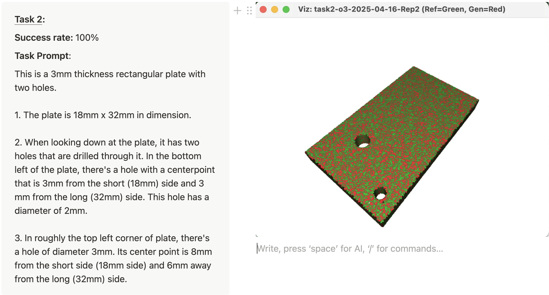
This is a 3mm thickness rectangular plate with two holes.
The plate is 18mm x 32mm in dimension.
When looking down at the plate, it has two holes that are drilled through it. In the bottom left of the plate, there’s a hole with a centerpoint that is 3mm from the short (18mm) side and 3 mm from the long (32mm) side. This hole has a diameter of 2mm.
In roughly the top left corner of plate, there’s a hole of diameter 3mm. Its center point is 8mm from the short side (18mm side) and 6mm away from the long (32mm) side.
The benefit of this approach is that we can score each task as a Pass or Fail and we can do this in an automated way. I wrote 25 total CAD tasks which ranged in difficulty from a single operation (“A 50mm long pipe that has a 10mm outer diameter and 2mm wall thickness”) to 5 sequential operations. For each task, I designed a reference CAD model using Autodesk Fusion 360 and then exported a STL mesh file.
Then, I set about programming the automated eval pipeline (of course, I didn’t actually write much code).
Here is how the eval pipeline works:
- For each task and model, the eval sends the text prompt (along with a system prompt) to the LLM via API.
- The LLM sends back the openSCAD code.
- The openSCAD code is rendered into a STL
- The generated STL is automatically checked against the reference STL
- The task “passes” if it passes a number of geometric checks.
- The results are then outputted in a dashboard.
[Note: The eval runs multiple replicates per task x model combo. And the eval is executed in parallel, because there can be 1000+ tasks when running the full evaluation.]
Here’s how the geometric check works:
- The generated STL and reference STL are aligned using the iterative closest point (ICP) algorithm.
- The aligned meshes are then compared by:
- Their volumes (pass = <2% diff)
- Their bounding boxes (pass = <1 mm)
- The average chamfer distance between the parts (pass = <1 mm)
- The Hausdorff distance (95% percentile) (pass = <1 mm)
- To “pass” the eval, all of the geometric checks must be passed.
There are a few areas where the eval pipeline could be improved. In particular, false negatives are common (est: ~5%). I’ve also noticed that occasionally, small features that are incorrect (like a small radius fillet) are not caught by the automated geometry check. Nevertheless, the eval pipeline is still good enough to see interesting results and compare the performance of the various LLMs.
If you’d like to learn more about the eval, use it, or check out the tasks, please check out the GitHub repo.
Finally, there are a number of ways to improve the evaluation. Here are a few things that I’d like to do next:
- More tasks with greater coverage
- Optimize system prompts, in particular by adding OpenSCAD documentation and code snippets
- Create an eval variation that uses sketches and drawings as input
- Add another variation that tests the ability of the LLM to add operations to existing OpenSCAD script and STL
- Evaluate the ability of the LLM to fix mistakes in an existing STL / OpenSCAD code
Rapid improvement of frontier models
Here are the results from an eval run executed on April 22, 2025. In the eval run, 15 different models were tested on the 25 tasks with 2 replicates were task. All of the results and configuration details from the run are available here.
The results show that LLMs only became good at OpenSCAD solid modeling recently.
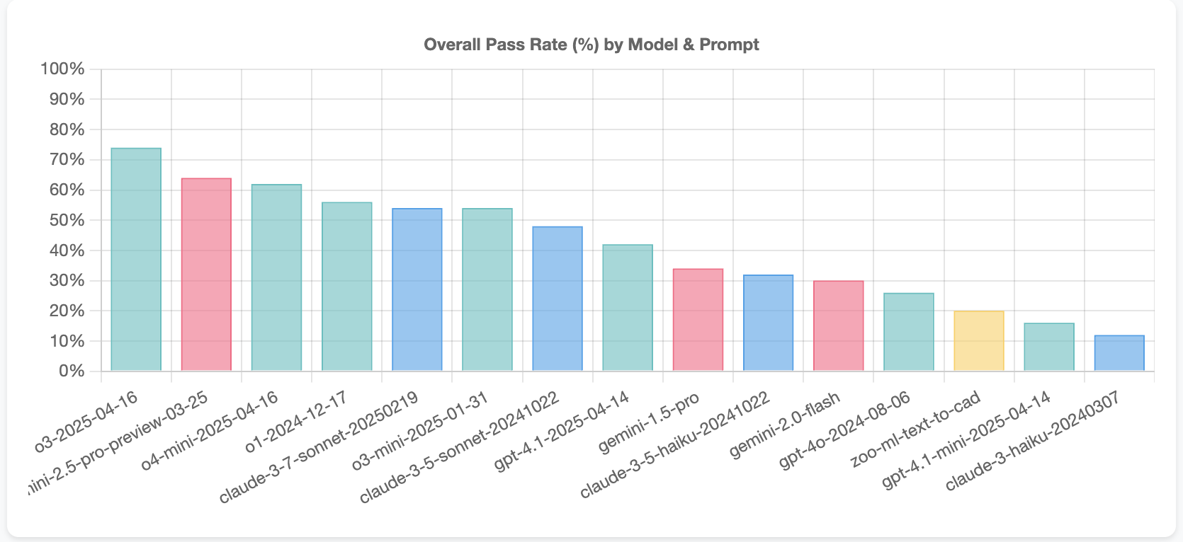
The top 3 models were all launched while I was working on the project and the top 7 models are all reasoning models. These models offer large performance increases compared to their predecessor, non-reasoning counterparts. Sonnet 3.5 is the best non-reasoning model and Sonnet 3.7 is only slightly better performing in the eval (for Sonnet 3.7, thinking was used with a budget of 2500 tokens).
Digging into the results offers some interesting insights. First, the LLMs are quite good at generating OpenSCAD code that compiles correctly and can be rendered into a STL. In other words, only a small portion of the failures are coming from things like OpenSCAD syntax errors. Anthropic’s Sonnet models are the best at this.
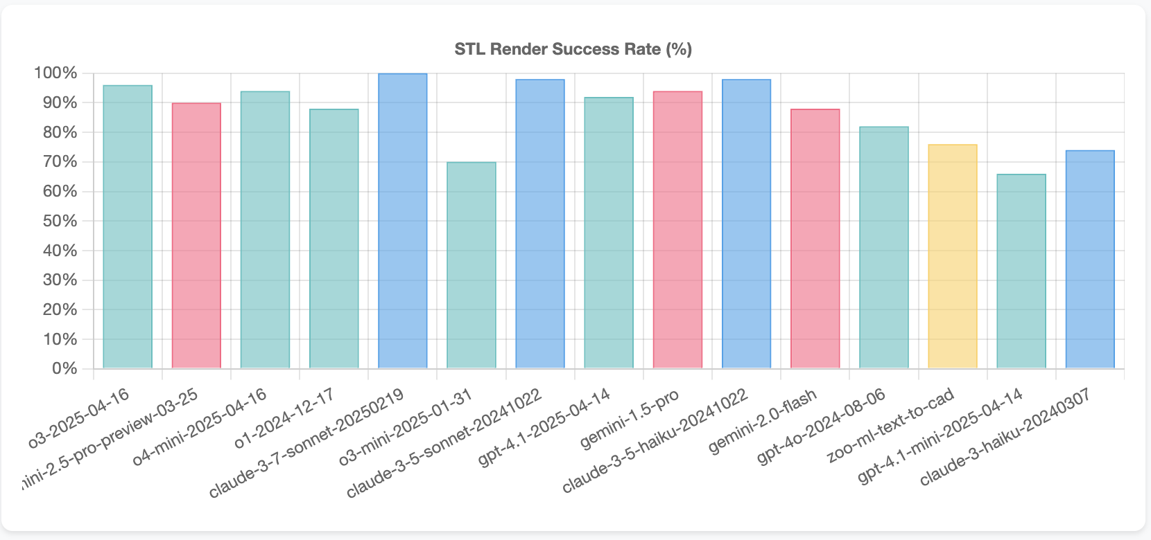
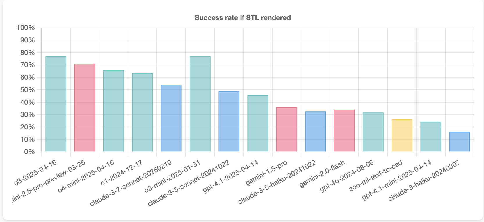
Additionally, we can look at the success rate for tasks where a STL was rendered. The o3-mini is quite strong, with nearly the same sucess rate as the full-size o3 model, while Sonnet 3.7 appears to be a step behind the leading Gemini 2.5 Pro and o1, o3, o4-mini, and o3-mini models.
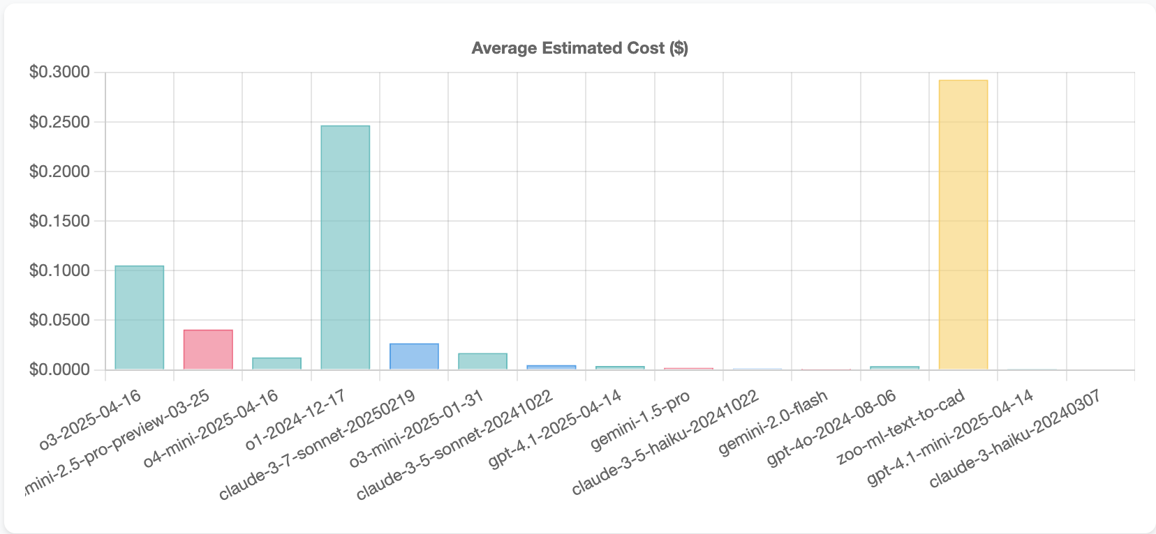
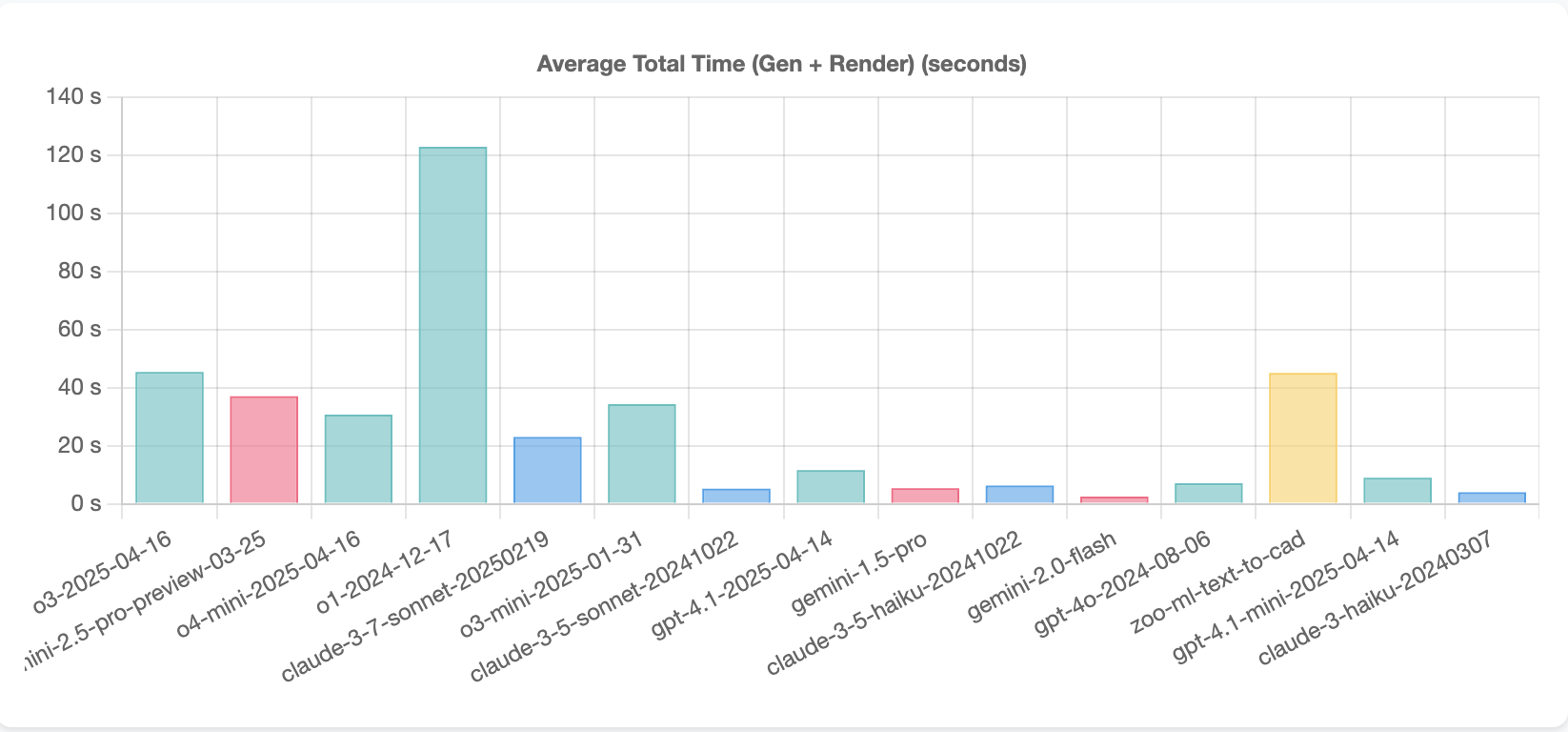
Finally, to be expected, Gemini 2.5 and o4-mini are substantially cheaper and slightly faster to run than the full o3 and o1 models.
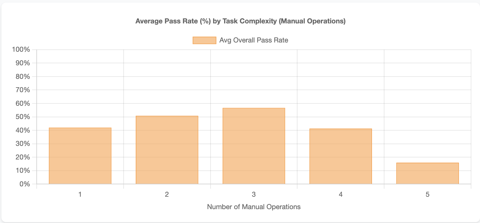
As expected, some tasks were easy and some tasks were hard to complete.
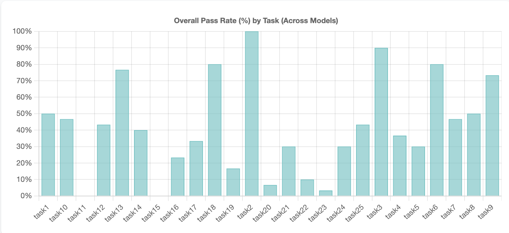
Generally, speaking tasks with more operations we’re more challenging.
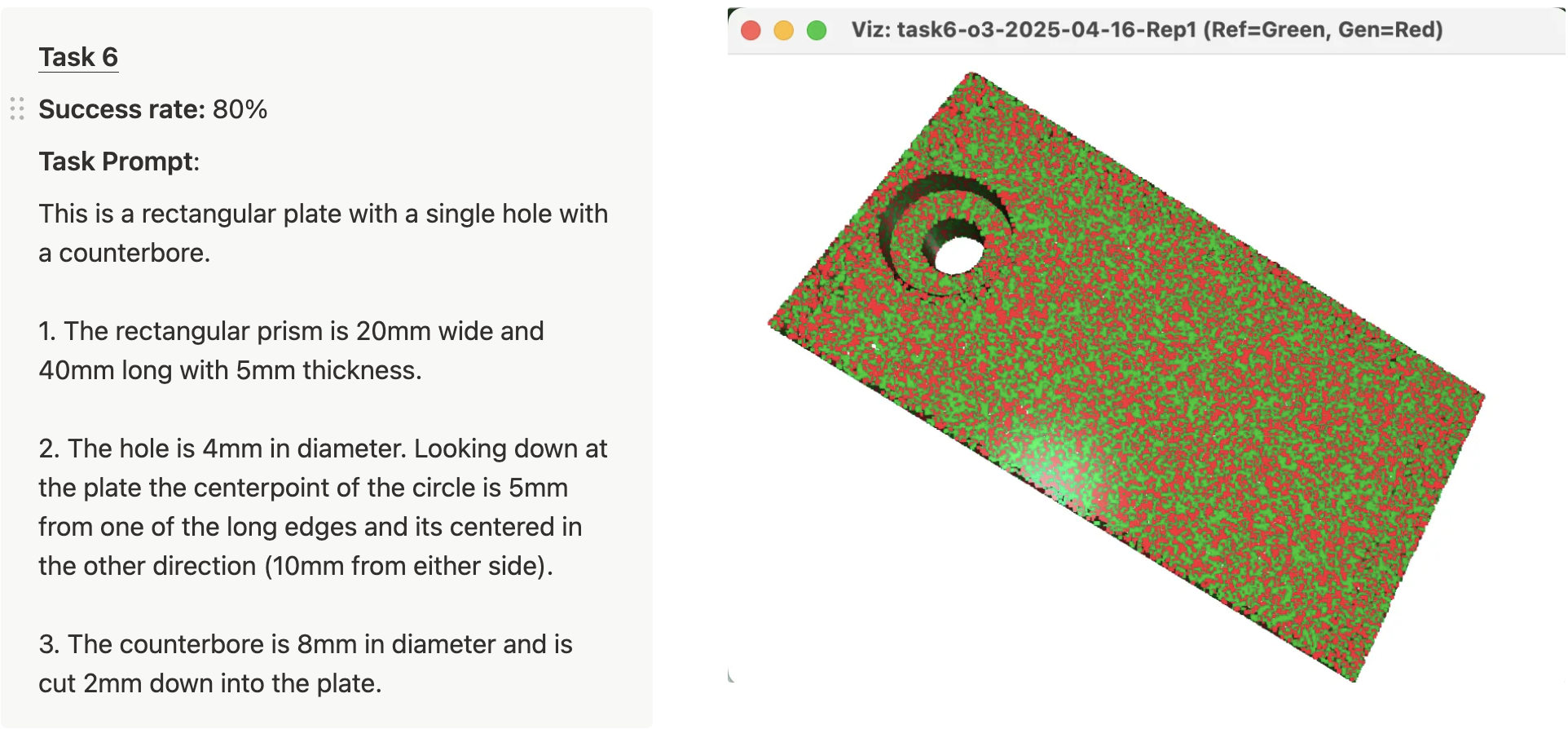
Tasks 2, Task 3, and Task 6 were the easiest tasks with over 80% correct across models. Here’s what these tasks looked like with example successes.

Only 2 tasks had 0% success, task 11 and task 15. Here are the prompts for those two tasks and representative failures.
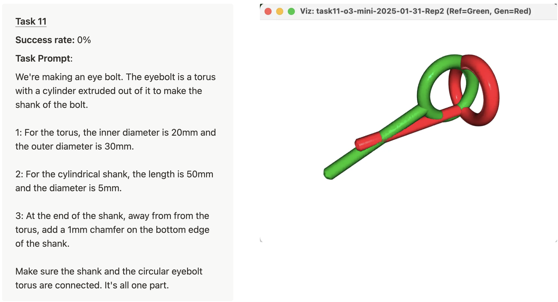
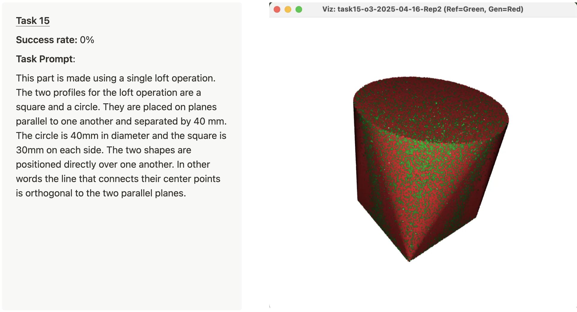
These failures are both interesting and quite different. Task 11 is a good example of poor spatial reasoning. In the specific failure highlighted in the image, the model extrudes the shank of the eyebolt orthogonally to the torus (instead of in the same plane). Task 15 is a different failure mode. It’s hard to see in the attached image, but if you zoom in closely, it’s clear that the generated shape is slightly larger than the reference shape (which makes sense, because the generated STL failed the volume check). From looking at the OpenSCAD code for this example, it appears that the failure is due to using OpenSCAD’s hull operation, which is not precisely the same as a loft operation. OpenSCAD does not have a loft operation built-in.
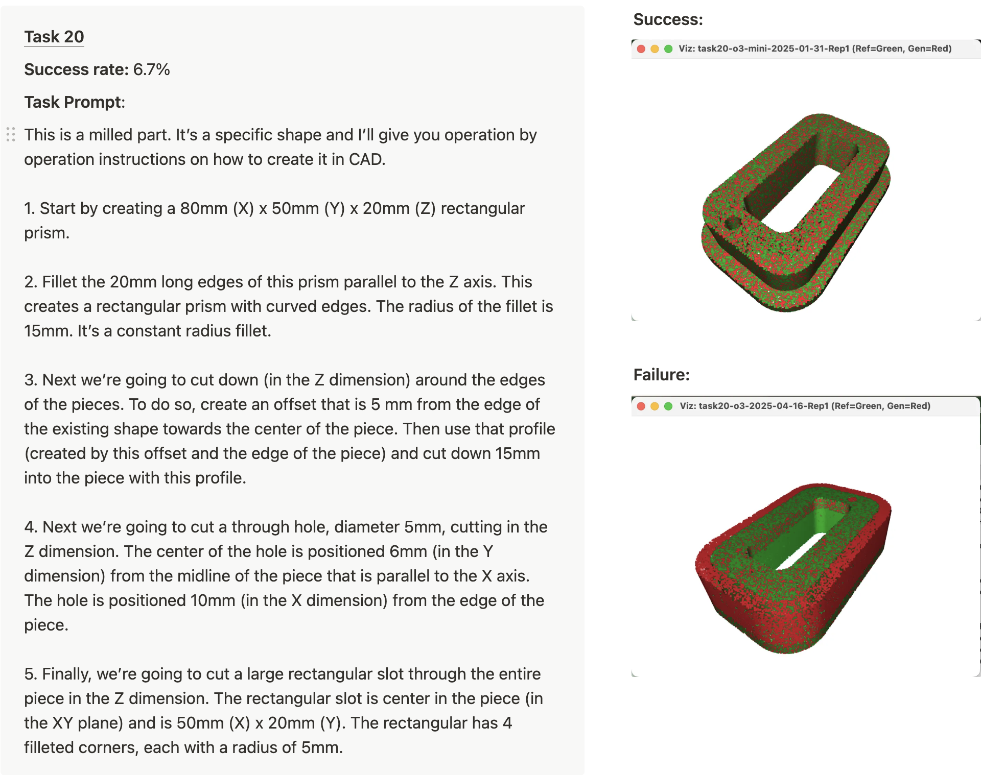
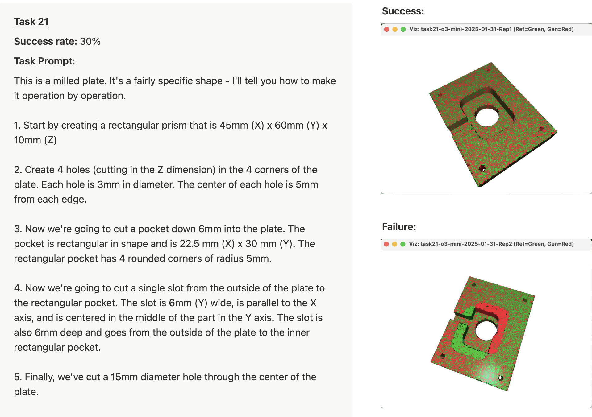
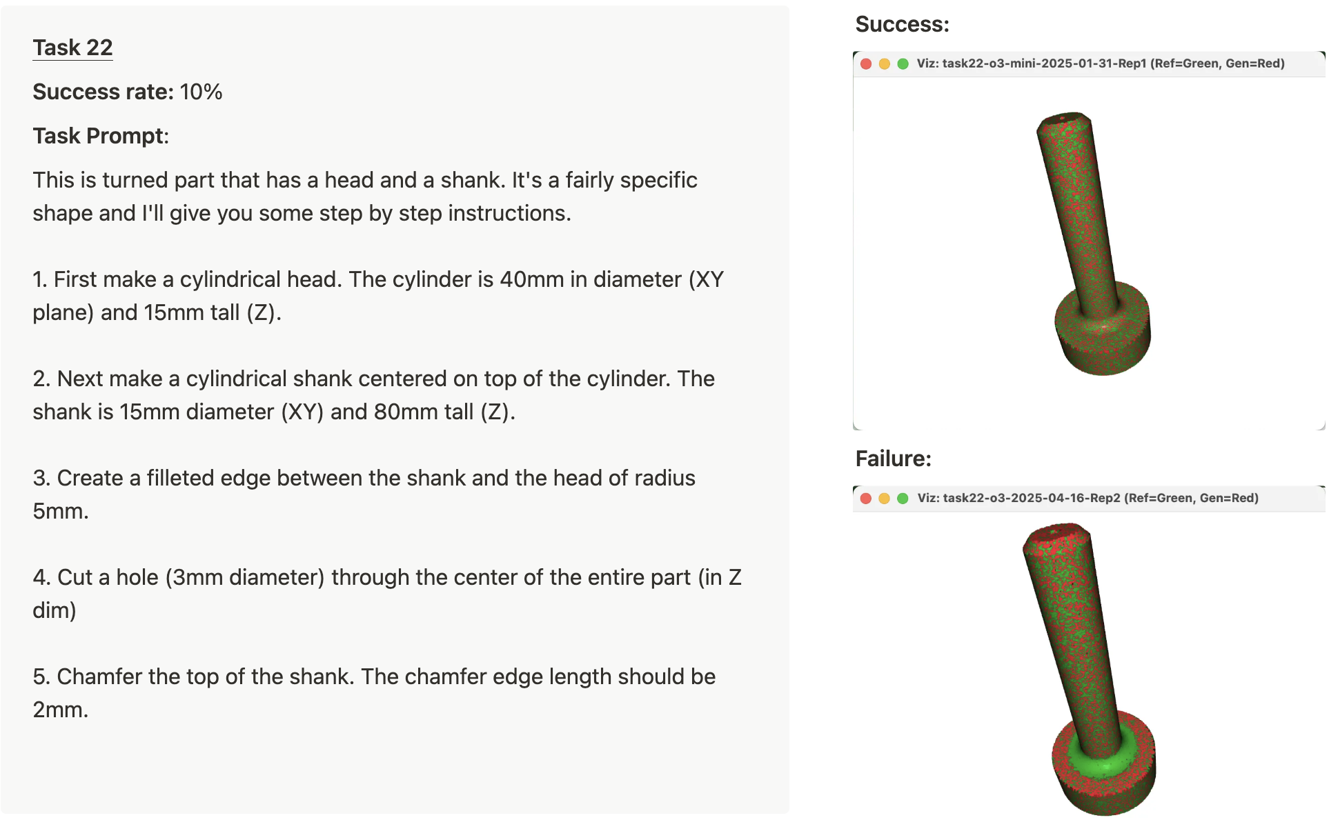
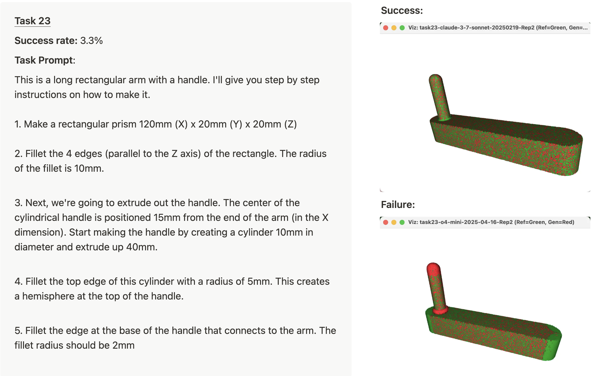
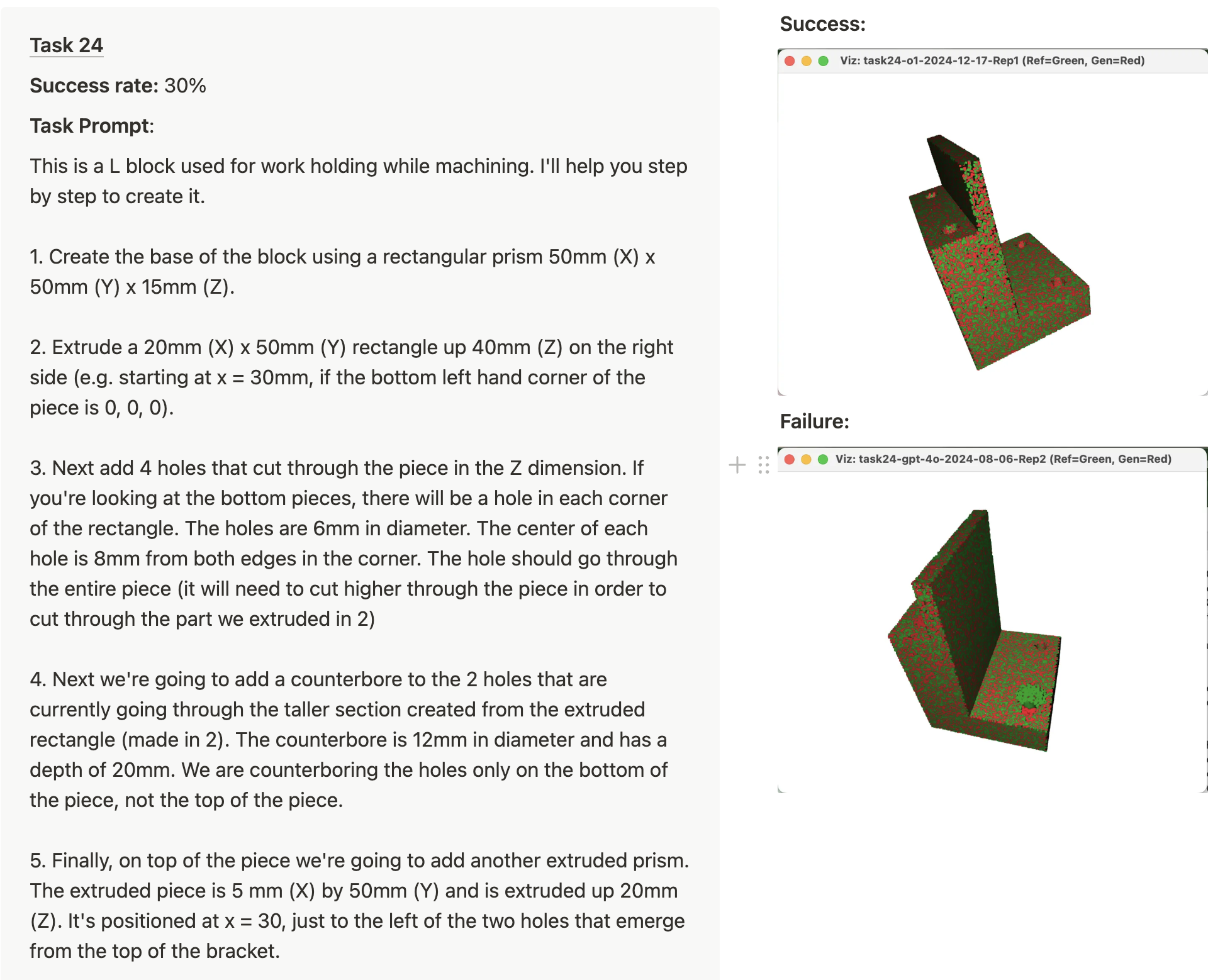
Tasks 20-24 all required 5 sequential operations and the average success rate for these tasks ranged from 3.3% to 30%. Here are the prompts for those 5 tasks with representative successes and failures.
The failures can be tricky to spot. The green areas of the failed images should have geometry in the generated STL, but do not (the reference point cloud is plotted in green). Likewise, the red areas have geometry in the generated STL, but they shouldn’t.
Start-ups
In the past few months, two different start-ups launched text-to-CAD products, AdamCad and Zoo.dev. Zoo.dev offers an API to use their text-to-CAD model. Zoo’s demos of their API and text-to-CAD product are very cool and look quite similar to the Cursor -> OpenSCAD demo I have above.
We're excited to announce the launch of Zoo.dev, a text-to-CAD API that lets you generate 3D models from text descriptions.
— Abhishek (@abhi1thakur) July 21, 2024
We've been working on this for the past year, and we're finally ready to share it with the world.
Here's a thread on what we've built 🧵 pic.twitter.com/Yd9Yd9Ixqm
I added Zoo into the eval pipeline to compare against LLM -> OpenSCAD -> STL. Instead of generating OpenSCAD, the Zoo.dev API shoots back a STL directly. Zoo says they use a proprietary dataset and machine learning model. To my surprise, Zoo’s API didn’t perform particularly well in comparison to LLMs generating STLs by creating OpenSCAD. Despite that, I’m excited to see the development of Zoo.dev and I will be eager to see how future model launches from Zoo.dev compare to LLMs creating OpenSCAD.
What’s next?
I think these initial results are promising. Cursor (or another coding agent) + OpenSCAD offers a solution for producing solid models in an automated way.
However, I don’t think this approach is about to take off and spread rapidly through the CAD design ecosystem. The current set-up is seriously clunky and I think substantial product improvements are needed to make this work better. Similar to how Cursor, Windsurf, and other tools have developed specific UX and LLM workflows for code generation, I imagine there will be substantial work required to develop workflows and UX that make sense for CAD generation. Here are a few ideas that I think could be worth pursuing in this direction:
- Tools that bring in console logs and viewport images to Cursor from OpenSCAD for iterative improvement and debugging.
- A UI to highlight (and measure) certain faces, lines, or aspects of a part, which are fed to the LLM for additional context.
- Drawing or sketch-input, so the user can quickly visually communicate their ideas.
- A UI with sliders to adjust parameters instead of editing the code.
Additionally, I expect that further model advances will continue to unlock this application. In particular, improving spatial reasoning is an active area of research. I imagine that improved spatial reasoning could greatly improve models’ ability to design parts step by step.
So when does text-to-CAD become a commonly used tool for mechanical engineers? With start-ups actively building products and the rapid improvement of frontier models, my guess would be something like 6-24 months.
Where does this go?
In the medium to long term (2-10 years), I imagine that most parts will be created with a form of GenCAD. Allow me to speculate.
- Initially, GenCAD will be used to create parts that fit within existing assemblies. For example, you might say: “I need a bracket that fits here.” And, the GenCAD tool will create a bracket that perfectly joins with the existing assembly components. Want to analyze three variants with FEA? Ask for them. I expect mainstream CAD suites (Autodesk, Solidworks, Onshape) to add these capabilities directly into their product suite.
- Longer term, I imagine GenCAD will reach every aspect of a CAD suite: sketches, mates, assemblies, exploded views, CAM tool-pathing, rendering visualizations, and CAE. Imagine a design review where you highlight a subassembly and say “replace these rivets with M6 countersunk screws and regenerate the BOM.” The model, drawings, and purchasing spreadsheet all update in seconds.
We’re watching CAD begin to exit the manual-input era. I, for one, am quite excited about that.